-
Xuntong specializes in testing services for electrical accessories, consumer electronics, lighting, wireless, toys and other products.



 Service Hotline 18617145297
Conducted Harassment Resistance Test (CS)
Overview of immunity to conducted disturbances
This standard mainly introduces the test methods of the international standard IEC61000-4-6:2006, which corresponds to the national standard GB/T17626.6: 1998 “Electromagnetic compatibility Test and measurement techniques-Immunity to conducted disturbances induced by radio frequency fields”.
Purpose and application of conducted disturbance immunity test
The main source of disturbance involved in this standard is the electromagnetic field generated by radio frequency transmitters in the frequency range of 9kHz to 80 MHz. The electromagnetic field will act on connecting lines such as power lines, communication lines and interface cables of electrical and electronic equipment. The length of these connecting leads may be equivalent to several wavelengths of the interference frequency. Therefore, these leads become passive antennas, accepting the induction of external electromagnetic fields, and the lead cable can couple external interference into the inside of the equipment through conduction (and finally the near-field electromagnetic interference formed by radio frequency voltage and current enters the inside of the equipment) to cause interference to the equipment. Thereby affecting the normal operation of the equipment. Therefore, the purpose of this standard is mainly to establish a public reference for evaluating the immunity to conducted disturbances induced by radio frequency fields, and to provide a basic reference for professional technical committees or users and manufacturers of relevant products.
Common terms for immunity to conducted disturbances
(1)artificial hand
An electrical network that simulates the human impedance between the handheld electrical device and the ground under normal operating conditions
(2)auxiliary equipment
Equipment that provides the required signals for the normal operation of the equipment under test and equipment that inspects the performance of the equipment under test.
(3)injection clamps
u current clamp
A current converter realized by a secondary winding composed of a cable into which a signal is injected.
u Electromagnetic pliers
An injection device that combines capacitive and inductive coupling.
(4)common mode impedance
The ratio of common mode voltage to common mode current at a port.
(5)coupling coefficient
The ratio of the open-circuit voltage (EMF) obtained at the EUT port of the coupling device to the open-circuit voltage at the output of the signal generator
(6)coupling network
A circuit that transfers energy from one circuit to another with a specified impedance.
(7)decoupling network
Prevent measurement signals applied to the equipment under test from affecting the circuits of other devices, equipment or systems that are not being measured.
(8)voltage standing wave ratio
Ratio of the maximum voltage along the line to the adjacent minimum voltage amplitude.
Conducted disturbance immunity test level
u In the frequency range from 9kHz to 150 kHz, no measurement is required for inductive disturbance caused by electromagnetic fields from RF transmitters.
u In the frequency range of 150kHz to 80 kHz, the immunity test to inductive disturbance caused by electromagnetic fields from the RF transmitter shall be selected according to the corresponding test level according to the electromagnetic environment in which the equipment and cables are finally installed according to the table below.
Frequency range 150kHz–80MHz
test levels
| Frequency range 150kHz to 80MHz | ||
| test levels | Voltage (effective value) | |
| U0,dBμV | U0,V | |
| 1 2 3 X |
120 130 140 |
1 3 10 |
| specific | ||
| 1) X is an open level | ||
Ø Category 1: Low-level radiation environment. Typical levels for radio stations/television stations located at distances greater than 1km and typical levels for low-power transmitters and receivers.
Ø Category 2: Moderate electromagnetic radiation environment. A low-power portable transmitter and receiver used in close proximity to equipment (typically rated less than 1W). Typical business environment.
Ø Category 3: Severe electromagnetic emission environment. Used for handheld transmitters and receivers (≥2W) that are relatively close to the equipment but less than 1m away. High-power broadcast transmitters used in close proximity to equipment and equipment that may be close to industrial, scientific, and medical equipment. Typical industrial environment.
Ø Category ×: × is the level of openness specified by negotiation or product specifications and product standards.
u For equipment with an overall size of less than 0.4m and without conducting cables (such as power wires, signal wires or ground wires), the standard stipulates that this test is not required. For example, if a battery-powered device is not connected to the earth or any other equipment and is not used while charging, this experiment is not required. However, if the device is also used during charging, this experiment must be done.
u The frequency range specified in the standard is 150kHz-80MHz, but the actual test frequency range can be determined after analysis based on the situation of the equipment under test. When the size of the equipment under test is relatively small, the test frequency can be extended to a maximum of 230MHz.
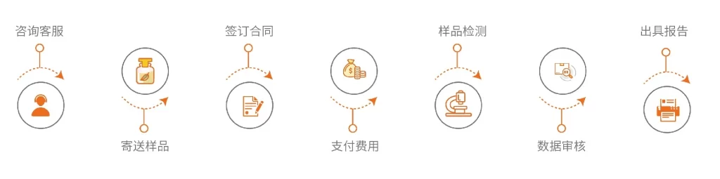
service process
 WeChat


 Submission Successful
 WeChat Official Account