-
Xuntong specializes in testing services for electrical accessories, consumer electronics, lighting, wireless, toys and other products.



 Service Hotline 18617145297
conductionInterference (CE)
Overview of conducted emissions
Conducted emission is usually also called a disturbance voltage test. Any product with a power cord will be involved in conducted emission testing, including many DC power supply products. In addition, signal/control lines also have requirements for conducted emission in many standards, usually used The limit of disturbance voltage or disturbance current (the two have a mutual conversion relationship) is expressed, and the insertion loss test in lamps (directly expressed in dB) also belongs to the category of conduction testing.
Conducted emission test standard
CISPR22 (ITE), EN55022,GB9254CISPR14-1 (household appliances and tools), EN55014-1,GB4343
CISPR13(AV),EN55013 ,GB13837
CISPR15 (lamps), EN55015 GB17743CISPR11 (ISM), EN55011
EN61326
EN60601-1-2
EN301489
PART 15
PART 18
YY0505
GB/T 18268
GB 4824
Conducted emission test method
1)Conducted emission test instruments and equipment: Receiver, LISN (Line impedance stabilization network, or AMN artificial power network), simulated hand, passive voltage probe, current probe (CDN used in conjunction with current probes, capacitive voltage probes), DIA (intermittent interference analyzer, used to test intermittent interference in CISPR14-1), a complete set of equipment for measuring insertion loss, etc., of course, PC is also indispensable. DIA needs to comply with the requirements of CISPR16-1-1, and other auxiliary equipment needs to comply with the requirements of CISPR16-1-2.
2)Conducted emission test arrangement: It is divided into desk and floor standing. The desk equipment is 80cm away from LISN and 40cm away from the grounding plate (The grounding plate here can be a horizontal grounding plate or a vertical grounding inner wall of the shielded room.) The distance from the floor-standing equipment to the grounding plate has different deviations depending on different standards. CISPR14- 1, 15 is 10cm +/- 25% inside, up to 12mm inside 13, up to 15cm inside 22, there is no clear distance in 11, only saying that it needs to be separated from the ground plate with insulating material. The layout of auxiliary equipment also varies according to test standards. In CISPR22, auxiliary equipment is 10cm away from the main equipment, and the interconnection wires between them are at least 40cm away from the ground plane. Hand-held Class II equipment requires a simulated hand. Self-ballasted fluorescent lamps in CISPR15 require an auxiliary conical metal cover.
3)Conducted emission test bands: Most are 150kHz-30MHz, with the exception of CISPR15 (disturbance voltage 9kHz-30MHz, insertion loss 150kHz-1,605kHz).
4)Conducted emission test limits: Limits vary with different standards and different product categories (Group 1/2, Class A/B).
5)Conducted emission test process:
a) Interference voltage at the AC/DC power supply side: This is the most common. Connect the power plug to LISN, connect the receiver RF input to the RF output of LISN (an RF attenuator or pulse limiter may be inserted in between), and switch the LISN L/N switch to select the common-mode disturbance voltage to ground of the test power line.
b) Intermittent interference: Requirements for CISPR14-1 and some standards that cite CISPR14-1. A discontinuous interference analyzer is usually used to measure in conjunction with LISN. The standard also allows a combination of an oscilloscope and a receiver to be used instead. The oscilloscope observes the duration of the disturbance, and the receiver observes the disturbance level and magnitude.
c) Load-side disturbance voltage: Requirements in CISPR14-1, CISPR15 and CISPR11. Use a passive voltage probe to strip off the insulation of the load line that needs to be tested, and directly use the probe to connect the receiver to measure the disturbance voltage of the load line wire terminal to the ground. Add that if the rated current of the equipment is too large and no suitable LISN is available, a voltage probe can also be used directly to measure the disturbance voltage at the power supply side.
d) Communication line disturbance voltage/disturbance current: mentioned in CISPR22. There are different test methods for different types of communication lines. Annex C has a detailed description, and Annex F has an analysis of the advantages and disadvantages of various methods. It mainly relies on different combinations of current probes and CDN, 150 ohm ground resistance, and capacitive voltage probes to test different types of communication cables. The prerequisite to ensure is that the ground impedance of the test cable is 150 ohms. The result can be directly expressed as the disturbance current dBuA, or it can be converted into the disturbance voltage dBuV. The converted impedance is 150 ohms, that is, the difference in magnitude between the two is 44dB.
e) Insertion loss: mentioned in CISPR15. Use an RF sine wave generator to pass through a balanced/unbalanced converter, analog lamp, LISN, and finally use a receiver to measure and compare the voltage to get the insertion loss value.
Determination of conducted emission test results
The measured value (QP/AV) of the receiver detector is compared with the limit line, and is lower than the limit line PASS and higher than FAIL.
Considerations for conducted emission testing
Because the conducted emission test is a common mode disturbance measurement to the ground, the key lies in the test layout. If the conducted emission test layout is fine, just use the receiver to test it. Differences in the conducted emission test layout will lead to differences in the results. Outstanding issues: Use of pulse limiters at the RF input of the receiver: Some testing organizations use them to protect the receiver; some resist, believing that the limiter contains nonlinear elements to limit the pulse, causing intermodulation distortion and generating harmonic form disturbance. Affecting test results. Try not to use personal opinions, although no actual comparison has been made.
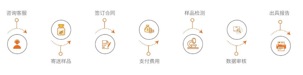
service process
 WeChat


 Submission Successful
 WeChat Official Account