-
Xuntong specializes in testing services for electrical accessories, consumer electronics, lighting, wireless, toys and other products.



 Service Hotline 18617145297
Failure of electrical products often leads to incidents such as electric shocks and fires that damage personal and property safety. Therefore, in safety testing, fault testing is an important part. The method is to artificially set some faults to assess whether the product can safely fail when a fault occurs. If possible, then even if the product fails during normal use, no accidents will occur, which is equivalent to adding an important layer of safety to the product.
This paper takes the fault test of self-ballasted LED lights as an example to introduce in detail the test conditions setting, determination of test procedures and result judgment of fault test, providing reference for product developers and testers.
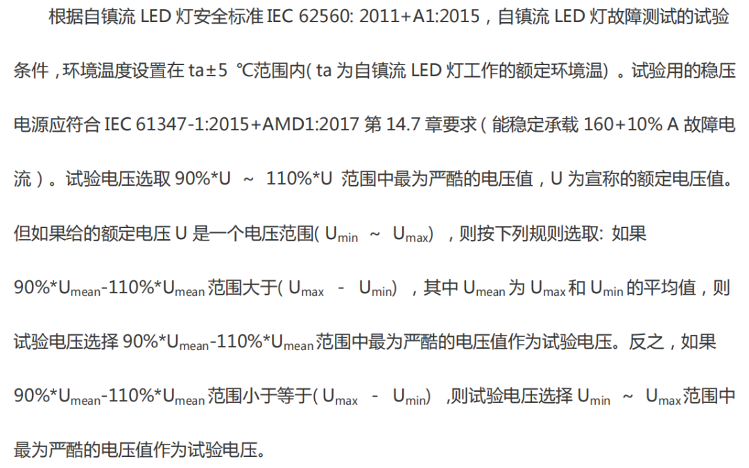
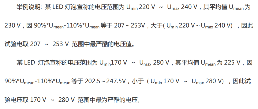
1. test conditions
2. test procedure
Set the fault, let the lamp head face up so that the lamp can be powered on normally in a free state, and wait until the lamp’s state reaches a stable state before letting the previously set fault take effect. After the fault takes effect, allow the lamp to continue to operate for 8 hours under the fault conditions. Finally, whether it is qualified is determined based on the phenomena occurring during the test.
2.1 Fault setting and circuit analysis
The setting of LED bulb failure means that components that may cause danger are shorted or opened. Follow the principle of single fault setting, only one component can be performed at a time, and there is no need to perform short circuits or open circuits on several components at the same time. Fault settings are generally performed on electrolytic capacitors, diodes, between two adjacent pins of the IC chip (no test is required for non-adjacent pins), LED driving output terminals, etc. Since the circuit may be completely damaged after the fault is implemented and cannot be restored to use, the recoverable faults should be arranged together as much as possible and verified one by one to avoid wasting time by constantly replacing new circuit boards. Generally speaking, for components closer to the input end, the possibility of failure causing damage to the circuit board that cannot be recovered is higher. Therefore, it is recommended to set the fault from the output end first and then proceed in the direction of the input end during testing.
For example, common non-isolated buck high-frequency switches control LED bulbs, integrated circuit ICs (built-in MOS tubes) serve as switch tubes. The working principle of this circuit is that the high-voltage sine wave is rectified by the rectifier bridge, and then subjected to electrolytic filtering to become a fluctuating DC voltage. The DC voltage passes through the LED lamp beads, the inductor, and then through the IC’s switch tube (conduction) and sampling resistance. Return to the DC high-voltage ground to form a loop. After being turned on for a certain period of time, after the IC switch tube is turned off, the energy stored in the inductor is directly discharged to the LED through the diode. The switch tube is turned on and off continuously cycles. Coupled with the effect of large-capacity electrolysis at both ends of the LED, the current flowing through the LED is a Relatively constant DC keeps the LED lamp beads in working state. If the circuit is not analyzed, but random components are shorted or opened, the test will be interrupted at any time due to exploding plates. The correct approach should be to put the recoverable components together from the output end to the input end. For example, after the IC( VCC,ROVP) is shorted, the switch tube is in an disconnected state and will not be burned out. Therefore, these faults can be carried out on the same circuit board. After each fault is cancelled, the circuit board will return to normal. There is no need to replace the board, and the next test will be carried out directly. For example, after the rectifier bridge stack is short circuited, the fuse resistor is burned out due to overcurrent, and the circuit board cannot continue to be used, so these tests should be carried out last. If the two pins of an IC( CS, DRAIN) are shorted, the IC or the fuse resistor will be burned out and cannot be recovered, so it should also be placed last.
2.2 Observation of failure phenomena
After the fault is implemented, the standard requires that the lamp be powered on and run for 8 hours. Because there are many faults that need to be set, this is unrealistic in operation. In actual operation, pay attention to the changes in lamp current and power after the fault is implemented. If the current and power become very small and do not increase for a period of time, there will be no fire or smoke even if the ignition continues for 8 hours. In this case, there is no need to click for 8 hours, and the next fault test can be completed in 30 minutes. However, if the power continues to increase after the fault is implemented, then the lamp must continue to operate for a period of time and continue to observe the worst possible results. If the power starts to decrease after a period of time, you can also end the test before 8 hours. It can be seen that after the fault is implemented, paying attention to the power trend can help greatly save test time. Of course, during the testing process, if the phenomena in the result determination in Part 3 of this article appear, the test can also be stopped immediately.
3. result determination
In the self-ballasted LED lamp fault test, if there is a fire or combustible gas is produced, or if the live parts become accessible, it will be judged as unqualified. During the actual testing process, combustible gas will generally not be produced, but smoke will be smoked. If there is smoke, it is generally judged as unqualified. On the contrary, if there is no such phenomenon, it will be considered qualified. It should be noted that if there is no failure during the fault test, but after the fault is implemented, if the power is maintained at a level higher than the rated power, a temperature rise test should generally be performed at the same time to evaluate whether each component can withstand the high temperatures caused by the fault test.
 WeChat


 Submission Successful
 WeChat Official Account